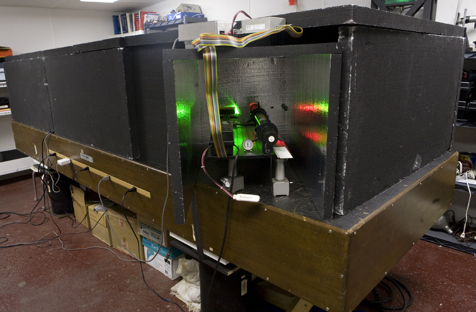
The Vibration Isolation Table is the altar upon which we melt our sacrificial incense of hot glue to appease the Gods of Mt Holympus. One of them, who goes by TJ, has blessed the Holography Studio of E. Wesly & Sons with a vintage Modern Optics 4 foot by 12 foot (1.2192 by 3.6576 meters) table with aluminum honeycomb inside, real wod paneling on the outside, complete with electrical sockets on both sides! The Styrofoam covers aren't hiding any secrets, they are there to shelter the experiments from drafts.
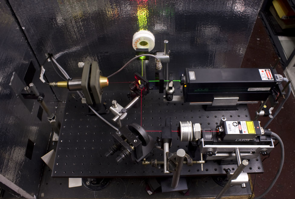
The above was how the table looked in 2011. For a the 2016 view, see here. Right here is the current view. At the east end of the table (for hopefully the optimal Feng Shui) are the lasers and their optics, with the lids off of their styrofoam boxes, which are made from garage door insulation, which has shiny foil on one side, which helps to reflect the laser's heat out of the open back of the enclosure and not radiating into the exposure area. Notice the pipes and flanges that bring the breadboards up to nominal beam height. I have adopted an "Offitial Beam Height" on my table of 12 inches, so that the typical American ruler can be used to check the level of the beams anywhere on the table. (Yes, I know offitial is spelled incorrectly, see here for the reason.)
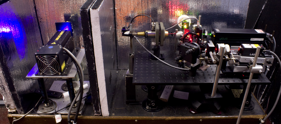
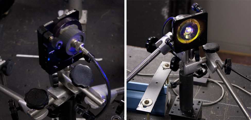
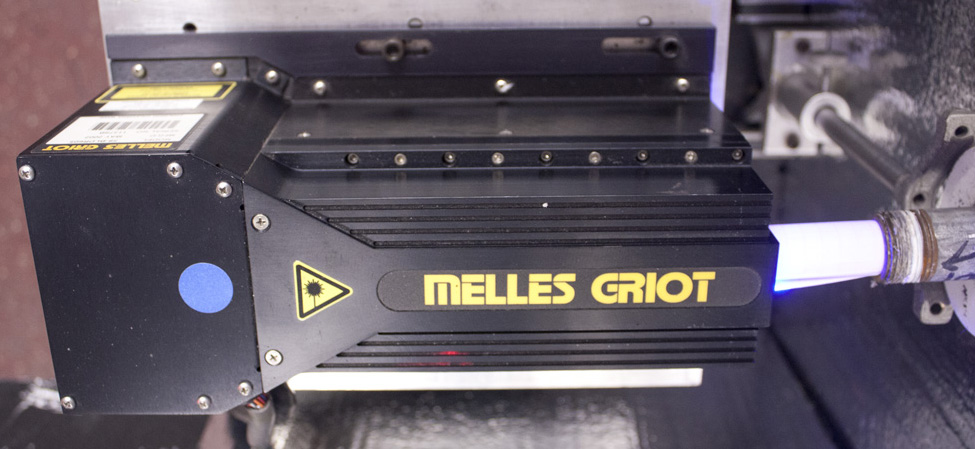
On the left is a Melles Griot BLD-605, emitting about 400 milliWatts of 458 nm blue in multiple beams. To the right, the green and red emitters share their enclosure.
All the lasers are mounted on breadboards that raise their beams to approximately the offitial height. Since both the red and green lasers are so compact, they are mounted to their shared breadboard by way of Newport Model F-91TSes, which pitch and yaw (to use aircraft terminology) the lasers and their beams. By moving the lasers themselves, one mirror in the beam path is eliminated, along with its losses and possible instabilities.
Here is a close up of the red laser, single longitudinal mode 200 mW at 640 nm, from Lasos of Germany their RLK 40200 TS. The fans had to come off the heat sink, as they shook the table, and are mounted on their own separate stand, not attached to the table but standing on the floor, still blowing and sucking through the heat sink.
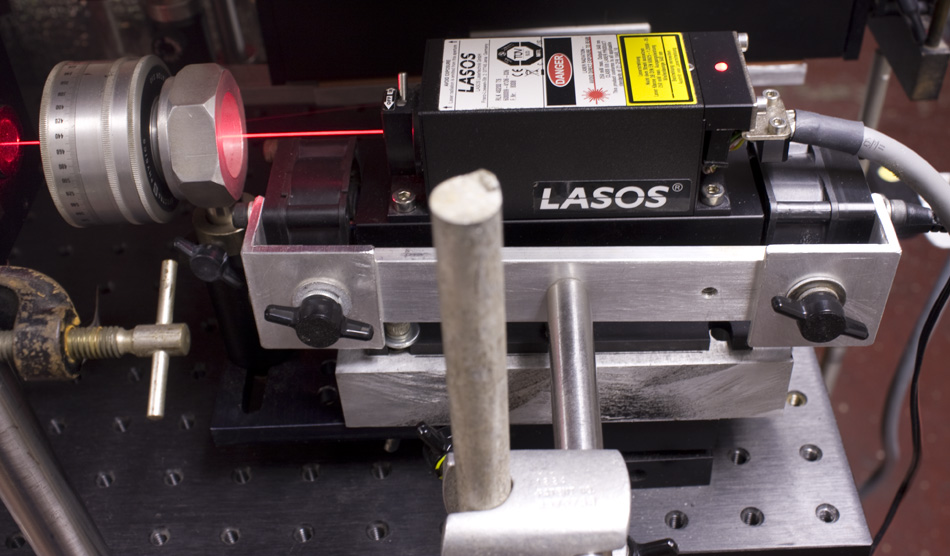
The laser is mounted by way of a big chunk of aluminum as a spacer and heat sink to a Newport Model F-91TS, which aims the laser and its beam. Also mounted to the movable laser base is its polarization rotator, a vintage golden nugget from Spectra-Physics, their Model 332, so that it remains aligned to the laser. After that is the red laser's shutter, a Uniblitz T132. It is mounted on a 7 kilogram steel casting, which will absorb most of the shock of the shutter opening, and it is sitting on top of a computer mouse pad, to dampen the vibration of the shutter further before it reaches the table.
Here is a close-up of the green laser, an Adlas DPY 315, 100 mW @ 532 nm, attached to the breadboard similarly to the red laser via a Newport Model F-91TS, with its half-wave plate also attached to the tilt-shift stage so that it stays aligned to the laser. Sharp-eyed viewers may notice that this retardation plate is not normal to the green beam, but tilted off-axis, and this not only eliminates the back reflection off the uncoated quartz sandwich entering into the resonating cavity but makes the plate that is wavelength specific for the 515 nm of the fire-breathing argon lasers of yore work at the 532 nm of the frequency doubled Nd:YAG. Tilting the plate increases the internal path length, so that the slightly longer wavelength fits a whole number plus a 1/2 wavelength in the wave plate, so that its polarization vector can be rotated through the miracle of birefringence.
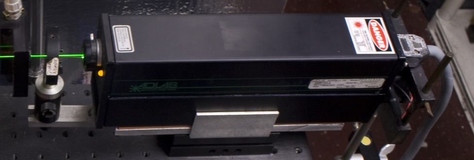
The shutter for this laser, another Uniblitz, their Model SD-10, is after the wave plate, its opening click dampend by another heavy cast iron base sitting on a mouse pad like the other lasers.
The fan that had been inside this laser's heat sink was removed and attached to its own floor stand, so that its vibrations were not transferred to the table and obliterating the contrast of the fringes as seen by the fringe stabilizing system, just like the Lasos. It sucks the air through the heat sink, the same direction it was headed when the fan was in the middle of the heat sink, sucking in one end and blowing out the other.
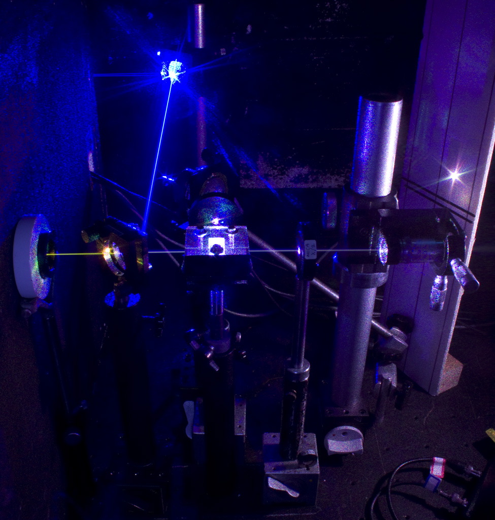
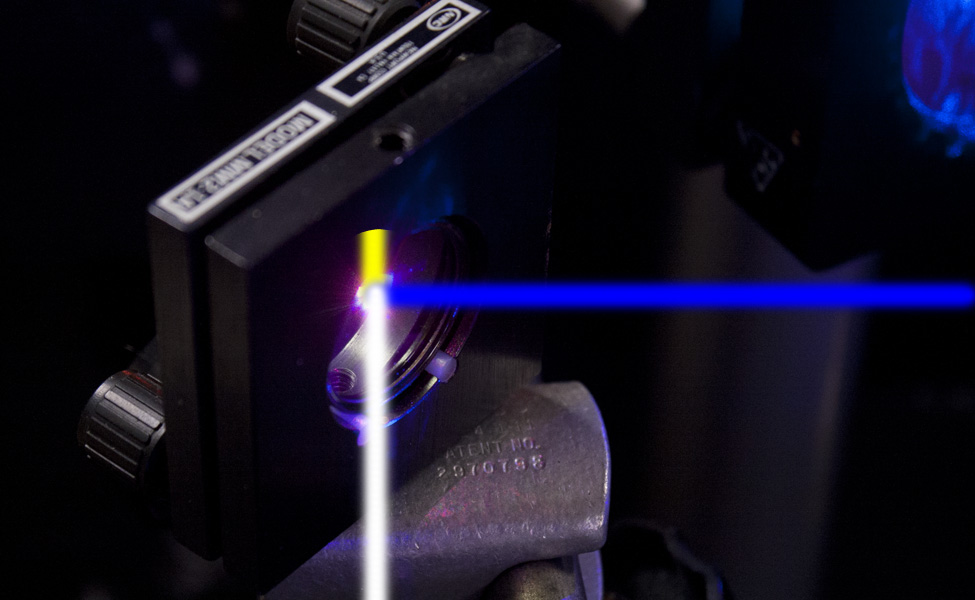
This is the overview of the red and green lasers' breadboard. Starting at the bottom right is the Lasos on its stage with its attached λ/2 plate, and its fans, unattached. The red beam passes through the shutter, and makes a 90° turn thanks to a Modern Optics mirror that has been upgraded with a pair of Newport 80 pitch thread screws and a marble as its pivot point. Then it joins up with the green beam at a dichroic beamcombiner, which reflects practically all the 532 nm and transmitting all the 640 nm red. There is a weak Fresnel reflection of the red off the plain glass side of the dichroic, and this beam is not wasted but goes into a Spectra-Physics Model 470 Scanning Fabry-Perot Spectrum Analyzer to keep an eye on the Lasos, as sometimes it is up to some funny business, like mode-hopping.
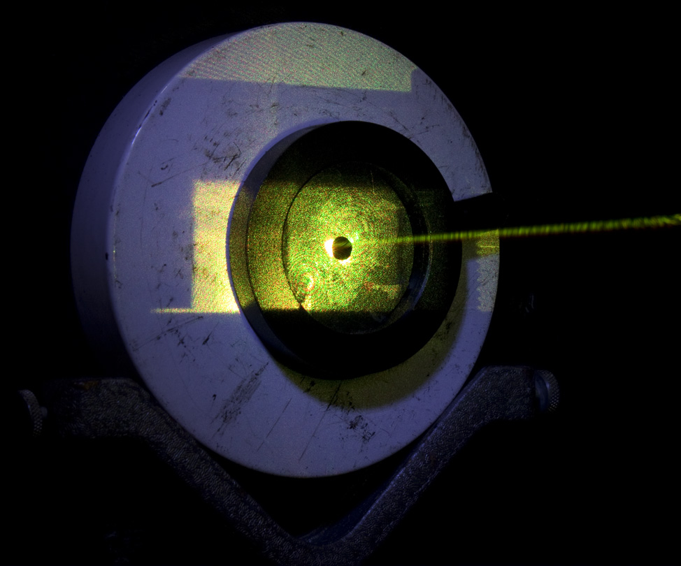
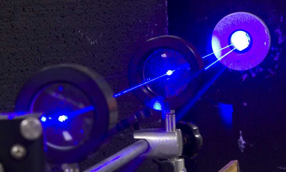
After the dichroic mirror is an iris diaphragm, whose post holder is screwed into the table top along the row of holes which defines the optical axis for the holographic setups, positioned precisely the offitial 12" above the table. Its twin is also screwed into the tabletop along the same row of holes, its aperture also exactly the same height above the table. The green laser is pitched and yawed and the dichroic mirror is tilted and pivoted so that the beam is walked in to thread both the eyes of the needles of the two apertures. Once the dichroic is set, then the red laser is pitched and yawed and its mirror is tilted and pivoted so that it, too, is threading both needle eyes, making a yellow beam from their collinearity, over a distance > 3 meters! With this tight of an alignment, they can even go through the same pinhole on a spatial filter!
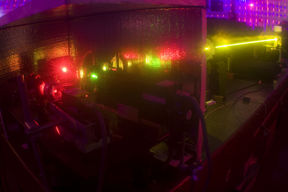
Heading northwards, or counterclockwise around the table, the comined red and green beams pass out of the laser box into the work space through and iris diaphragm which is stuck on a magnet to put it in a position to let the beams out but a minimum of turbulence from the heat and the fans of the lasers. Notice all the back reflections it catches.
A splitting is usually what's in store for the laser beam after leaving the safety of the box for multiple beam holography. Although the Studio has some rotary beamsplitters, they are typically relegated to beamcombining for fringe stabilizing, as they have surprisingly high insertion losses, especially at their more reflective sections, which would probably not take lightly to the combined output of a half a Watt of RGB. The preferred method of dividing a beam here is with the use of half-wave plates and polarizing beamsplitting cubes. That is why each laser has its own λ-specific retardation plate in rotating mounts after them, so that each laser's beam balance ratio is independent of the other ones.
Then the beams encounter the Broadband Polarizing Beamsplitting Cube, sitting on a Newport MM-2 mirror mount mounted on its back. One of the beams exiting is reflected off the cleave in the center of the cube, so there is a need to control the direction of that beam, and a mirror mount under the cube fits the bill in tilting the cube. A plexiglass dust cover keeps the cube clean. The unit is mounted on a 1" diameter steel rod screwed into the table along the row of holes that define the optical axis of the holographic set up, so it's not going anywhere, which is most important, as the path length differences.that define the holographic pattern start here.
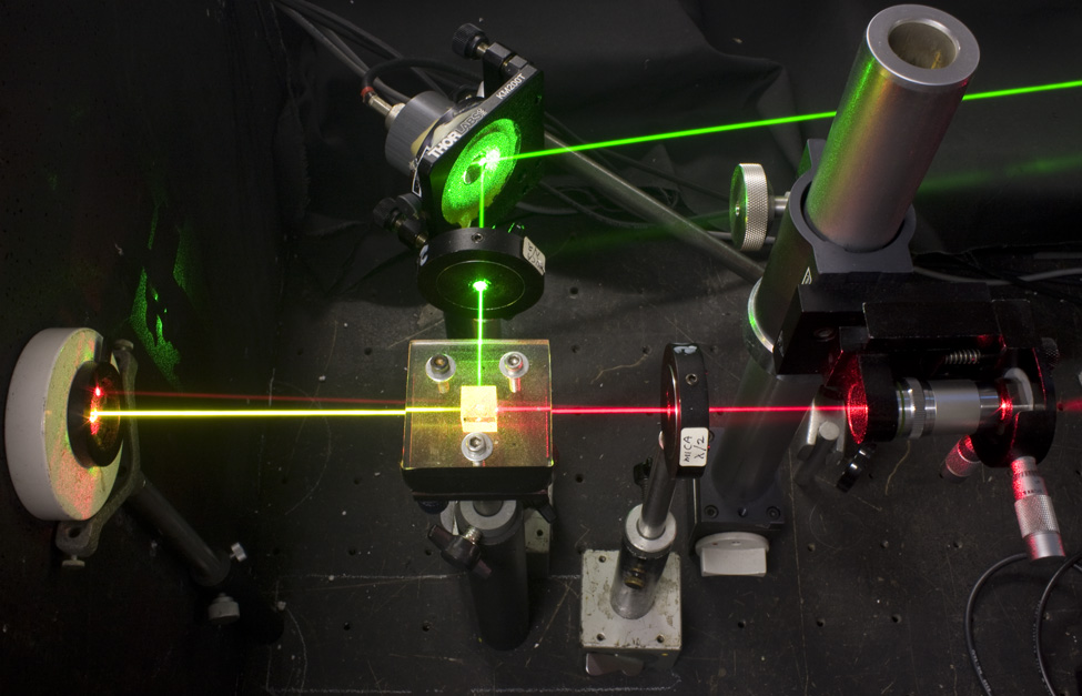
In the photo above, the polarization rotating half-wave plates of the lasers in their box are set to transmit mostly the red through the cube and reflect green out of the cube. Half-wave plates are positioned in both the reflected and transmitted beam paths to rectify the alignment of the polariztion vectors coming out of the cube; the transmitted beam is mainly horizontally polarized (in the frame of reference of this table set up) and the reflected one is vertically polarized. These half-wave plates are not wavelength specific quartz like the ones following the lasers inside the box, but mica, which is somewhat broadband, necessary for controlling multiple wavelength collinear beams. The disadvantage is that the mica is a bit cloudy compared to the quartz, wasting light, so the waveplate that doesn't need to rotate the polariztion to match the other is usually removed. The rotating mounts for these plates were made in the shops of Lake Forest College.
Above the reflected output beam's half-wave plate in the photo above, mounted in a ThorLabs Model KM200T Mirror Mount, is the "Electric Mirror" of the Fringe Stabilizing System. It can be placed anywhere along the output beam path that the recording geometry dictates, and is securely cross-braced to the tabletop.
The blue laser has not been forgotten, just need to back-track to the east end of the table, to find a Melles Griot BLD-605, 400 mW at 458 nm, sitting in its own compartment: BLD stands for Blue Low-noise Dual, and it emits a pair of equally strong single longitudinal beams coherent with each other. However they are not shown in this view, as they are inside the beam tube to protect the two beams from the rush of the cooling airflow directly under them, as the refractive index change between the hot and cold air causes the beam to wander.
After exiting the blue laser's box, one of the beams enters into a Beam Shaping Telescope, as prescribed by Laser Sam.
Then the beam takes a right turn off of a Newport Model 625A Mirror Mount and heads for a long wavelength pass, short wavelength reflect, dichroic mirror, which mixes the 458 nm photons with the 532 and 640 ones and adds up to white.
Here is the beamsplitter/combiner mirror mount, with red and green pass, blue reflecting dichroic to combine all three beams into white:
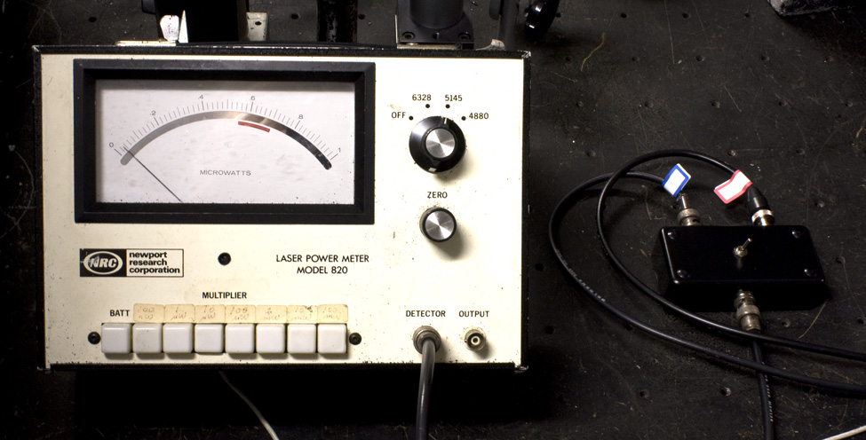
An ancient Newport Model 820 Power Meter resides under the shade of the beamsplitting cube. The Radio Shack Project Box with all the BNC connectors selects between one of two photo-detectors at the other end of the table. One could be placed behind the far iris to peak the placement of the bright Gaussian center of the laser beam through it, as in the double threading of the needle image above, or to measure the incident flux in the plateholder. Being right next door to the red and green lasers' box makes it easy to control the Beam Balance Ratio by simply sticking one's hand inside the box and rotating the half-wave plate and comparing the readings of the reference and object beams on the 820.
A recent project was to make a Holographic Optical Element with the red and green lasers. One beam came from one side of the holographic plate along the normal from approximately 2 meters; the other beam came from the other side at 45 degrees from the normal. The long path starts at the left of the picture below, and the other beam is at the other end of the table.
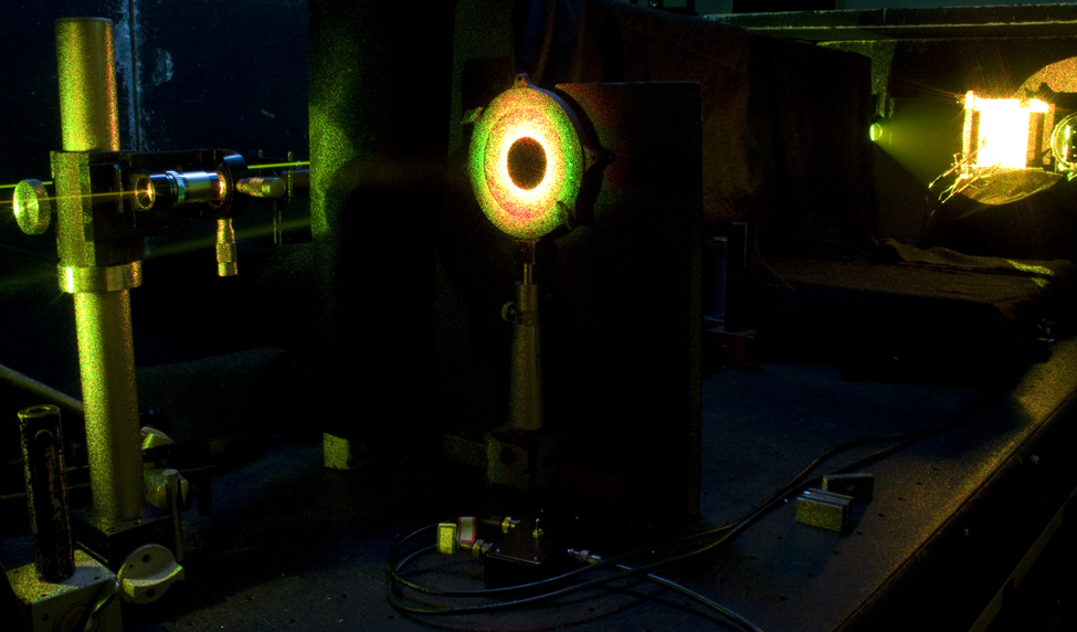
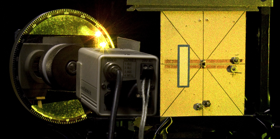
The a piece of cardboard with 2 photo cells is loaded in the plateholder at the upper right, being illuminated from both sides Immediately to its right is a Newport Rotary Beamsplitter being used as a beamcombiner in this case, to generate fringes for the fringe stabilizing system. Here is the set up as seen from its side:
The long path is off to the left side, the short path from the upper right, and the beamcombiner is next to the plateholder, which is a Panavise. The Closed Circuit Television Camera without a lens is where the fringes are formed, directly on the sensor chip. This is looking over the camera's shoulder, and the top dot on the beamcombiner is the reflection of the short beam path, and the lower dot is the transmission through the beamcombiner of the long beam path. The rotary beamcombiner is rotated so that both the transmitted and reflected beams' intensities are equal, for the highest contrast fringes.
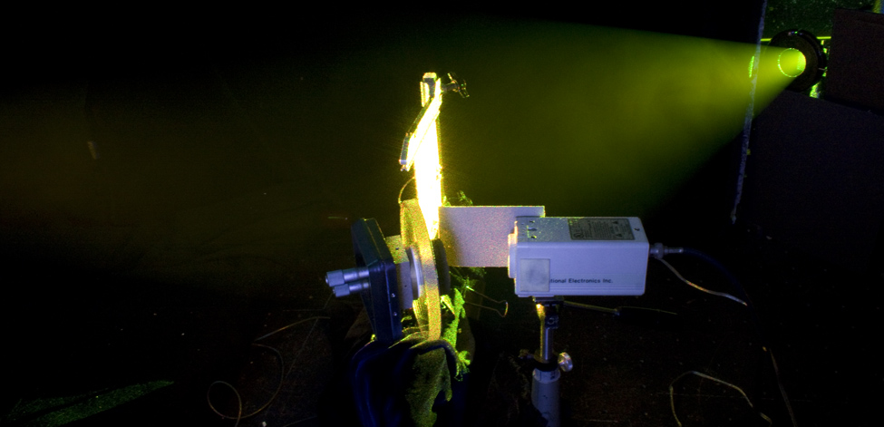
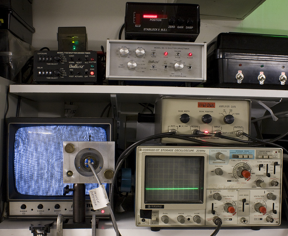
These fringes are displayed on the Closed Circuit Televison Monitor connected to the lensless CCTV Camera, and the Stabilock Fringe Stabilizer's Fringe Detector is placed up against the display to monitor the fringe displacement so that the Stabilock's Control Box can control the Electric Mirror to lock the fringes in position!
This lab is available for rental or commissioned work, please contact me at eweslystudio at gmail dot com!